One owner’s hands-on experience
By Robin Phipson
INTRODUCTION:
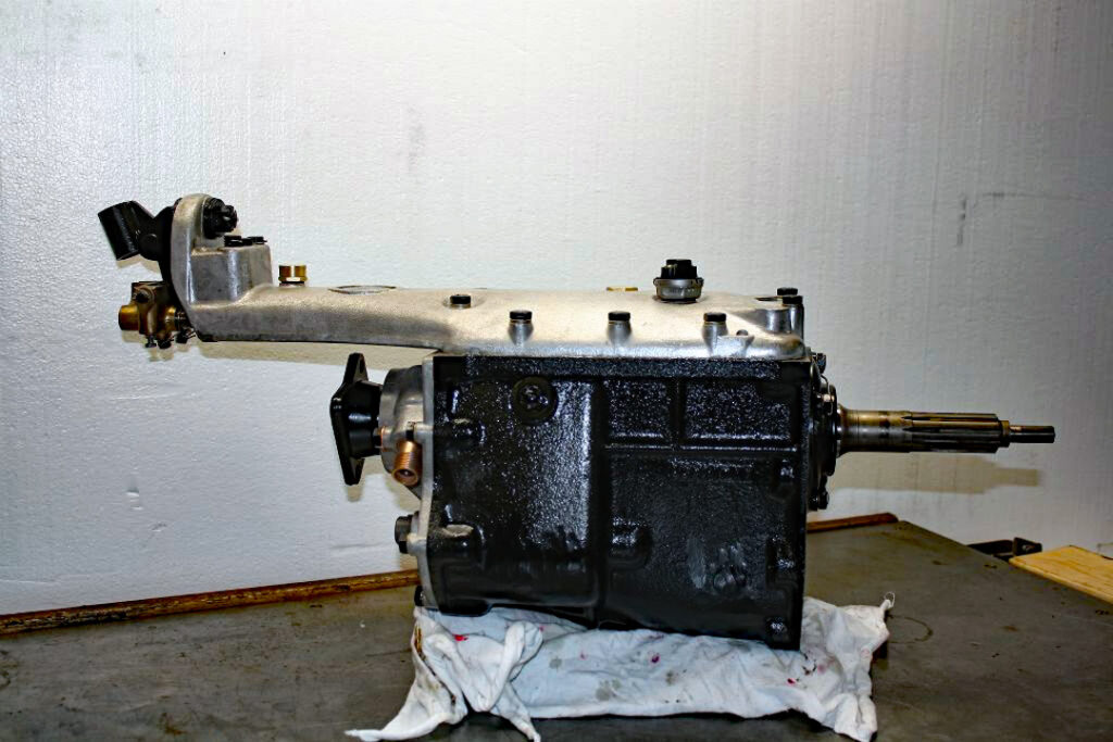
The Moss gearbox was fitted to essentially all manual Jaguars up to the mid-1960s, after which Jaguar’s all-synchromesh unit was fitted. The Moss box came in for much criticism over the years. Much of it was justified. The main problems were:
no synchromesh on first,
very noisy in first and reverse,
very low first gear,
poor synchromesh on second,
extremely long travel from first to second,
and an ability to leak oil from just about everywhere.
It did, however, have some good points: It was an extremely strong unit and very seldom did internal parts fail. It was extremely quiet in the top three gears and the low first could be very useful for awkward manoeuvring, towing and steep pull-offs. It also used SAE 30 engine oil, so that meant one less lubricant to buy.
Nowadays it is fashionable to throw out the Moss Box and put in either an all-synchro Jaguar unit, a Getrag box, or even a Cressida box. I will say upfront that I disagree with this approach. A good Moss box is not that bad if driven properly. It has a certain character which goes with the car. In any case, with the engine in good condition, you are soon in fourth gear and you just stay there, occasionally flipping in and out of overdrive for overtaking. It is also sacrilege to destroy a matching number Jaguar by putting in another gearbox. Why not just buy a Corolla? (I am ignoring you -ed)
The tossing of these gearboxes is also owing to restoration books’ just about never recommending overhauling them. They say just clean and paint the box and put it back. The rebuilt car then has a terrible gearbox and the owner hates it…
Admittedly, the Moss box is fiendishly difficult to overhaul properly due to its complex assembly sequence. It can, however, be done. Gearbox shops seldom, if ever, do the job properly as they have no specs, no manual and don’t know where to get the spares from.
The purpose of this article is to give you sufficient knowledge to overhaul a Moss box properly, so that it is even better than when it was new. You must have a copy of the factory workshop manual and follow it to the letter when stripping and assembling. There are, however, some errors and omissions in the manual and I shall cover them in this article.
PARTS REQUIRED:
The good news is that most parts required are available from any good bearing shop. Here is the list, with modern “bearing shop” part numbers and some Jaguar numbers. (Includes overdrive parts)
1) Factory workshop manual
2) Gasket set: cut your own from expensive 0,23 mm sheet or ENT101 – from SNG Barratt or similar supplier.
3) Spigot shaft bearing: 6308 NR
4) Mainshaft rear bearing: MJ 13/8 (May be different if no overdrive fitted.)
5) Circlip for securing item 4 above.
6) Mainshaft needle rollers: 82 off of NRA3.5×29.8
7) Layshaft needle rollers: 58 off of NRA3x23.8
8) Spigot-mainshaft caged needle roller: C1843 from any Jaguar spares place.
9) Spigot shaft shouldered oil seal: C18739 from any Jaguar spares place. (Do not use an unshouldered seal!)
10) Gear lever rubber grommets: two off of C1915 from any Jaguar spares place.
11) Synchro balls: 12 off of RB6.35
12) Synchro springs: 12 off of C900 from any Jaguar spares place.
13) Synchro spring shims: approx. 24 to 36 off of M3 flat washers.
14) Selector shaft balls: three off of RB6.35
15) Synchronising sleeve interlock balls: three off of RB6.35
16) Layshaft O-ring: 24 x 4 mm
17) Reverse shaft O-ring: R3062
18) Gear selector O-ring: R3050
19) Reverse/OD switch O-rings: two off of 4mm x 2mm
20) Speedo drive O-ring: R2081 (May be different if no overdrive fitted.)
21) Speedo drive oil seal: 0,375”x 0,75”x 0,25” double-lip seal
22) Overdrive rear output bearing: 6206
23) Overdrive inner output bearing: RLS10
24) Overdrive thrust ring bearing: KLNJ50 (50x90x11mm)
25) Circlip 90mm internal for item 23 above.
26) Circlip 47mm external for item 23 above.
27) Overdrive rear oil seal: 1,69”x2,5”x0,5” double lip seal
28) Overdrive control valve ball: RB7.938
29) Overdrive non-return valve ball: RB6.35
30) Overdrive accumulator sleeve O-ring: R4150
31) Overdrive main piston O-rings: two off of R4112
32) Overdrive actuating shaft O-rings: two off of R3031
33) Welch plugs small: two off of 7/16” diameter
34) Welch plugs large: six off of 5/8” diameter
35) Flat washers: about 40 x M8 plated (covers g/box and O/D)
36) Spring washers: about 40 x M8 plated (covers g/box and O/D)
37) Various split pins
38) Expensive grey Loctite silicone sealant.
39) Pratley liquid steel.
SPECIAL TOOLS AND NOTES:
The only special tools you need are a dummy shaft and a helper shaft.
WARNING: The dimensions given in the manual for the dummy shaft are incorrect! You need one rod 24,8 mm in diameter, and 204,5 mm long, and a small helper shaft also 24,8 mm in diameter and about 50 mm long. These are easily made from a piece of 25 mm pipe or rod. Without these two items you stand a chance of losing layshaft needles – and spacers falling out – when you refit the layshaft.
NOTE: All the bolts and nuts on the gearbox, bar the one securing the spigot rod locking plate, are BSF. These are just about impossible to get in SA. So, don’t lose any! The overdrive uses UNF threads, which are no problem. A proper spanner is required for the nuts and bolts as 13 mm is too small and 14 mm is too big. Obtain a spanner marked 5/16 BS and/or 1/4 W which is 13,5mm across flats. DO NOT MIX UP THE O/D AND G/BOX NUTS!
SUPPLEMENTARY NOTES TO WORKSHOP MANUAL:
1. LAYSHAFT
- If the end float exceeds 0,006” turn up a thicker bronze (not brass) spacer of the smaller of the two spacers, such that the end float is 0,002”.
- The solid steel rod on which the layshaft needles run may be worn on one side only. If not too bad, simply rotate it through 180 degrees which will present a new thrust surface for the needles. This requires cutting a keyway for the locking plate on the other side and drilling new oil holes in same. Much easier than it sounds. If badly worn, get a new one.
- The first gear teeth may be chipped. It is vital to carefully pencil-grind them back to a pointy shape again. This reduces stress and prevents the box from refusing to go into first; sometimes even at standstill.
- The layshaft must be very carefully assembled, using LM grease only, onto the longer dummy shaft, complete with needle rollers and all spacers, and then carefully lowered into the bottom of the casing with dummy shaft in.
2. REVERSE GEAR
Attend to chipped teeth as above.
3. OPTIMISING SYNCHROMESH OPERATION
This is the crucial bit that almost everyone ignores.
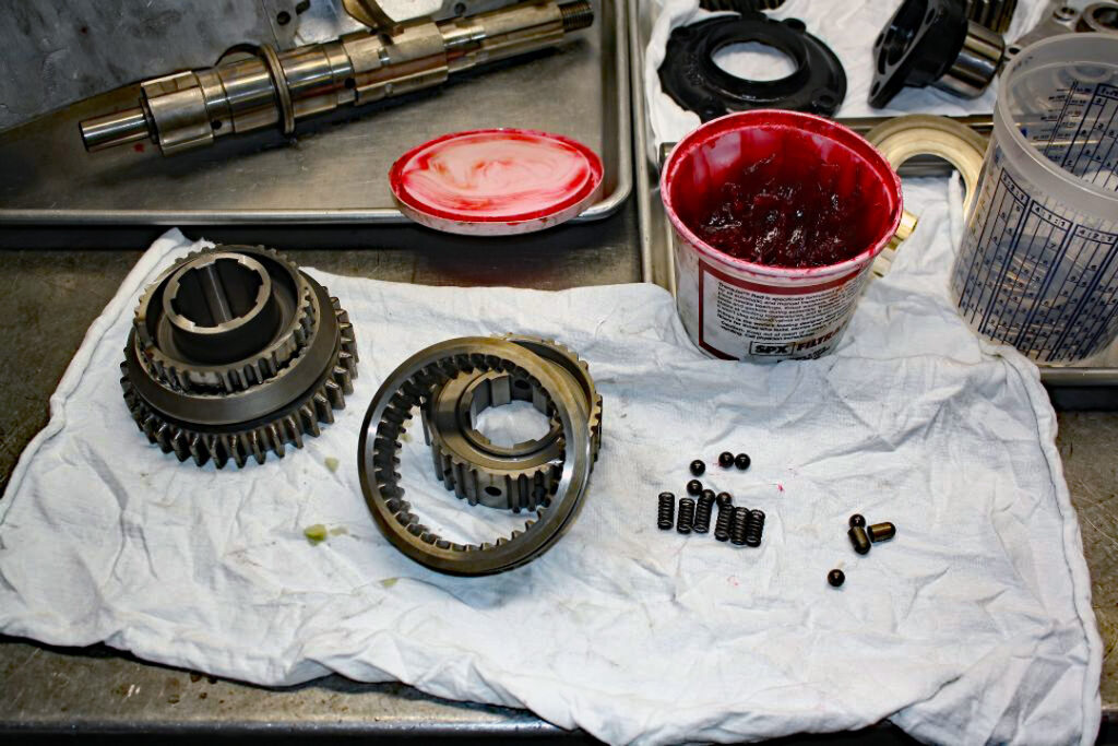
Let’s start with first/second gear synchro unit:
Remove the unit from the mainshaft. Note that a plunger and ball will fall inwards from the unit. Measure the length of this plunger with a micrometer (not a vernier!) and write the figure down. This is vital. Now put the unit into a transparent plastic bag and push the outer ring off the hub. Six balls and six springs will fly everywhere!
Dress any chipped first gear teeth as per the layshaft above.
Then, while working inside the plastic bag at all times:
Put two M3 flat washers into each hole, followed by the springs. Stick the balls in place with LM grease. Clamp tight with a large hose clamp and then, using a vice, press the outer ring onto the hub; compressing the six balls into the unit. If it will not go on, remove one M3 washer from each hole and start again.
Slide the outer ring so that the six balls click into the neutral detent. Now get your bathroom scales and press down on the outer hub in the direction of second gear. Take the reading off the scale at which the balls jump out of the neutral detent. The FIGURE MUST BE AT LEAST WHAT THE MANUAL SAYS OR YOU WILL HAVE TERRIBLE SECOND GEAR SYNCHROMESH OPERATION. If too little, you need more spacers under the springs but don’t let them get coil bound. This can all take ages, but I cannot over-emphasise the importance thereof.
Now put the aforementioned ball and plunger back in the unit and place back on main shaft. Hold the mainshaft with the tail vertically upwards and slide the outer ring into the first gear position. The second gear synchro cones should not rub in the slightest. If they do, a longer plunger is required. This can be done with a dab of low-hydrogen weld and then machining back in a lathe. Increase the length by not more than 0,005”. Again, I cannot over emphasise the importance of this. The plunger must also not be too long, or drag will result when changing from first to second, especially when hot.
4. Third/fourth gear synchro
Much more can go wrong here: Remove the unit very carefully, as before, from the mainshaft but this time note that there are two sets of balls and plungers that fall inwards from the unit. As before, measure and record them accurately and identify which goes into which hole. MIX THEM UP AT YOUR PERIL.
Fit six new springs and 12 x M3 washers as before, ENSURING that it passes the bathroom scale test. Try it in both directions. Again, I cannot overemphasise the importance of this.
Now refit the two pairs of balls and plungers and place the unit back on the mainshaft. Hold the mainshaft with the tail vertically downwards. Engage third gear. The free-float of the unit should be 2,4 mm and there should be no drag. (Drag is common on third even from new….) Fiddle the length of the plunger until these two conditions are met. (Third gear plunger is the one furthest from the front nose of the mainshaft.)
Now engage fourth gear. The free-float should now be 4,8 mm and, again, no drag and no third gear synchro rubbing. Correct as required. (Fourth gear plunger is the one closest to the front nose of the mainshaft)
Failure to carry out these interlock plunger corrections will result in possible sticky gear change, sloppy gear change, poor synchro operation and/or rapid synchro wear. YOU HAVE BEEN WARNED.
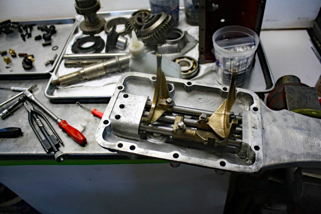
5. SELECTORS AND TOP COVER
Nothing is covered in the manual here…
- Reverse gear detent: Nothing spoils a Moss box more than it slopping over into reverse instead of first all the time. Rectifying this, and it has to be done, is very difficult. The detent spring brass assembly has to be removed from the selector shaft; which is much easier said than done. Once it is out, then beef up the springs as required until it requires a nice smack to get the gear lever across to the reverse gate. Keep sane!
- Ensure you change the O-ring on the outer selector shaft and epoxy seal the eight Welch plugs.
- Open up the O/D and reverse switches carefully, clean out and fit new O-rings in order to keep oil off the electrical contacts. Clean the electrical contacts with a sharp blade, or a fine-glass beadblasting. The correct fibre washer MUST be fitted under these switches, otherwise they will either make the selector shafts bind, or the switch will not be sufficiently pushed up to make proper electrical contact.
- The first /second selector shaft will in all likelihood have a steel washer crudely formed around it, at the rear, to prevent first gear from engaging too far. It is not shown in the parts manual, or in any exploded views. DO NOT REMOVE IT thinking that a monkey had fitted it. The selector detent seems to be slightly in the wrong place (factory fault) and full engagement of first gear can cause the six, second gear, synchro balls to become exposed and cause the car to jam in first gear. NB: The factory fitted this horrible washer as a quick fix… YOU HAVE BEEN WARNED.
- On the external selector bits, ensure that everyting is well lubricated. The big Thackeray washer should be at the front of the aluminium pillar. The small Thackeray washer should be at the left of the gear lever. Use common sense as to where the fibre washers should be. Failure to do so results in the gear lever being in a ridiculous position in neutral. Always fit new gear lever rubber grommets.
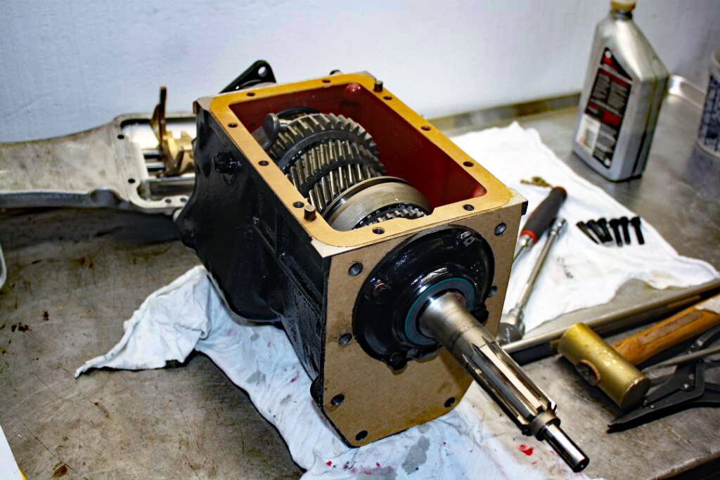
ASSEMBLY
This can be fiendish. Follow the manual, but do the following as well:
- Ignore the lifting of layshaft with screwdrivers. Once the mainshaft and spigot shafts are in, then lift the layshaft into mesh with two pieces of thin wire looped around each end of the layshaft and then, with your 50 mm-long dummy shaft, push the longer (204,5 mm) dummy shaft backwards until it goes about 10 mm into the casing. Leave both dummy shafts in. All is now safe and no needles and spacers can fall out. Ensure that locking pin of large front steel spacer engages with slot in casing.
- Fit layshaft rod and reverse rod to back cover using a smear of grey sealer as well as two new O-rings. Fit the locking plate and UNF bolt using grey sealer on threads of same. If you have turned the layshaft rod through 180 degrees ensure that the unworn face points upwards.
- Push above assembly into gearbox, simultaneously pushing out the two dummy shafts. Bolt up the back cover using a new gasket, flat washers and spring washers. Use grey silicone sealer sparingly. All surfaces should have previously been degreased with thinners.
- The mainshaft rear ball bearing, shims, spacer and circlip can be horribly difficult to get back on. Do not hammer, if stiff, as you will damage the bearing. Rather press it in with a hydraulic press. Very awkward!
- The top cover must have two dowel pins.
- Ensure bell housing bolts are very tight, locked and wired.
- Ensure the thrust bearing fork has both circlips to hold the thrust bearing. If the solid rod securing the fork to the bell housing is worn on one side, then turn it through 180 degrees so that the unworn parts thrust against the bronze bushes. Or build up with welding and machine down. Or make a new rod.
- Epoxy a magnet into the drain plug.
- After a few days, put some oil in the box and, with an electric drill on the spigot shaft, run it and change all the gears. Do this before fitting the overdrive.
CONCLUSION
Refitting to the overdrive, and overhaul of same, is adequately covered in the factory repair manual.
If you follow the workshop manual to the letter, except where otherwise stated in this article, and follow this article to the letter, you will end up with a Moss box that is actually quite pleasant to use. That is, of course, assuming it was not totally wrecked in the first place due to lack of oil, abuse etc.
Use only SAE 30 or SAE 40 engine oil. Despite what oil companies may say about modern gear oils, do not use them. The numerous bronze parts, and synchromesh operation, are adversely affected by the use of gear oils.
Finally, be wary of what is written on the Internet, various classic car magazines, and restoration books. A lot of it is written by armchair experts – many of whom can’t even spell Mark 2 – and much of it is a load of twaddle. For example, the book on rebuilding the XK engine contains, on average, about one error per page.
Views: 92
Leave a Reply